Voltage regulators are circuits for converting one DC voltage to another, and these days they are pretty easy to make. There are a wide variety of integrated circuits that make the job very simple. In this case, I wanted to run the NSLU2/QuickCam combination that I have been posting about from a 12V battery. It draws somewhere in the range of 600-1100mA, depending on whether or not the camera is running, so I need something that can convert an input that could be up to 15V (if the battery is being charged at the time), down to 5V, at up to 1.2A.
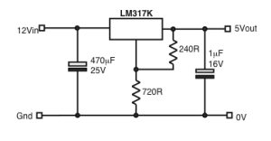
The simplest way of doing this is with a linear regulator IC, and a circuit like this:
The LM317 is actually an adjustable regulator whose output voltage is defined by the two resistors. The values shown yield 5V. The trouble with this design is that although its very simple – five parts – there is another component required which isn’t shown. Its a substantial chunk of metal that has to be bolted to the LM317 to act as a heatsink. It needs to dissipate up to 12W. This really means buying the LM317K version of the regulator and using a heatsink rated at 2°C/W or better, which is going to be a chunk of finned aluminium at least 100mm long. This has to be mounted somewhere and ventilated, and the regulator has to be bolted to it with an insulating pad and isolating washers. The simple circuit has turned into a piece of engineering, and all because its only 42% efficient at 12V. More than half of the energy supplied is being turned into heat. If we are running from a battery this is not good news.
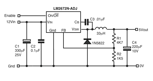
We can, however, do much better than this, by using a switching regulator IC. These used to be very tricky things to use, but modern parts have simplified the process to the point where they are relatively easy to apply. They do require some care in component selection and layout, but in return efficiencies are far higher, and no heatsink is needed. The circuit I have built is based on the National Semiconductor LM2672, and has all of nine components. It looks like this:
This design is about 88% efficient at 1A: 12V at 480mA in produces 5V at 1A out. The minimum input voltage at 1A is 7V, the maximum voltage before component changes would be advisable is 15V. The enable input can be left floating, or used to disable the regulator, if required, by pulling it down to ground. In the disabled state the regulator draws only 100μA. Enabled, but with nothing connected, the quiescent draw is 3.4mA. Again, its adjustable – the output voltage is set by R1 and R2.
I built this on a 46mm x 28mm piece of single-sided PCB material in about 30 minutes using a miniature electric hand tool to drill holes and rout channels on the copper side of the PCB. That was actually the easy part. The tricky bit is getting hold of the right components and putting them in the right places.
I think because switching regulators have had a reputation for being difficult in the past, they aren’t commonly used, so the components aren’t commonly about – so they aren’t often used, and so on. You will need to go to a larger electronics retailer to get the parts, and although none of them are particularly expensive, you will need to take care about the specifications of nearly all of them.
The LM2672N-ADJ is an 8-pin DIP package. Take care not to get the surface mount version, the LM2672M-ADJ, unless you like that kind of thing.
The 1N5822 Schottky diode is widely available in a DO27 package, but in this case you actually want the surface mount version for reasons I will explain shortly.
The 330μF (or more) input capacitor should be rated at 25V (or more) and at least 600mA ripple current. If the supplier doesn’t specify the ripple current, you should assume its not adequate. Good capacitors have a ripple current specification.
The 220μF output capacitor should be rated at 10V or more, and must be a high-frequency type with a low ESR at 100kHz. I used a Panasonic FC series part, EEUFC1A221, which manages 0.25Ω at 100kHz. The FM series are better, if you can get them.
C2 and C3 must be high-frequency ceramic types, preferably X7R. C2 can be more than 0.1μF, but C3 must be 0.01μF.
The inductor must be a type intended for use in switching power supplies, with a current rating of at least 1.4A. I used a TDK part, SLF12575T-330M3R2-PF, from RS Components. Its rated at 3.2A so was a bit of overkill and is larger than necessary. It is also surface mount which meant running a couple of wire loops through the board to solder it to, as it would have been awkward having it on the copper side.
The two resistors can be any 1/8W type.
Having got hold of the specified bits, the other critical consideration is the board layout. If this isn’t right, the regulator can be unstable in various exciting ways. Fortunately National Semiconductor have a comprehensive application note on the subject, AN-1229. Two components need to be as close as possible to the IC; the 0.1μF capacitor, C2, and the 1N5822 diode. The easiest way to achieve this is to mount the capacitor right beside pins 6 and 7, and the diode on the underside of the board right beside pins 6 and 8. The rest of the layout follows the National Semiconductor notes. Here is the back of the PCB before soldering, and the front after mounting the components.
The surface-mount 1N5822 is soldered onto the back of the board, directly under the IC, bridging the horizontal channel visible in the photo.
I have now built a couple of these and they seem to perform very well. They are probably best suited to digital circuitry as there is about 35mV of switching noise at 240kHz on the outputs, although this could presumably be filtered pretty effectively with an LC filter if it was a problem.


#1 by yeni on September 9, 2008 - 10:22 pm
This great blog.., how to adjust the voltage . I want adjust from 5 v to 25 volt .
Thanks
#2 by johnarthur on September 10, 2008 - 9:20 pm
I’m afraid this is a step-down regulator only; it can’t step up. Its adjustment range is limited to 1.2V to Vin-1V, roughly. To do 25V you would need something like the LM2577 – and a different circuit…
#3 by Lurch on May 8, 2009 - 10:41 pm
For those of us without the required skills to build one ourselves 😉 you can also get pre-built switching regulators – there’s a bunch of info and test results at:
http://sites.google.com/site/bifferboard/Home/howto/power-bifferboard-from-12vdc-battery
#4 by Coaxen on April 10, 2010 - 7:10 am
I have a question – what is the efficiency at lower output currents? The datasheet doesn’t specify anything other than the nominal efficiency at 1A.
#5 by johnarthur on April 11, 2010 - 9:36 am
I believe its pretty good; quiescent current (no load) is 3.4mA, so it scales well. If there is a specific value you would like to know about, I can measure it…
#6 by Tarun on June 12, 2018 - 1:31 am
is it possible to convert 15 volt to 13.7v
#7 by Lurch on June 12, 2018 - 11:58 am
Something like this https://www.amazon.co.uk/HiLetgo®-LM2596S-ADJ-Voltage-Regulator-Adjustable/dp/B00LTSC564 could convert 15 volt to 13.5 volt, if that’s good enough.